


urbancog
Active Member
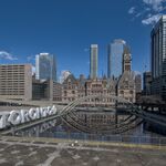
Looking at the bridge abutment configuration and the assembly photos, they may be building 4 separate bridge decks - two for Lower Jarvis, two for Lower Sherbourne. With each track sitting on ballast on a steel tray mounted on the cross beams, all supported by an I beam at each side.
Using MS-Word as a sketch tool:

Using MS-Word as a sketch tool: